
What is Optical Fluorescence Technology?
Introduction
Perfusionists use sophisticated technology every time they put a patient on cardiopulmonary bypass. Terumo is committed to developing products that incorporate pioneering technology in order to advance patient care. This article is the first in a series of articles that focus on these unique Terumo Technologies.
History of Optical Fluorescence
Professor Dietrich Lubbers, MD, of the Max Planck Institute in West Germany pioneered a way to measure substances in blood by combining sensor fabrication and chemical fluorescence technologies.
This technology was applied to blood gas monitoring by Cardiovascular Devices, Inc. (CDI), of Irvine, California, in the 1980s.
Today, this same technology is at the heart of CDI® Blood Parameter Monitoring Systems, which are manufactured by Terumo Cardiovascular in Ann Arbor, Michigan. Terumo’s CDI Systems use optical fluorescence and a reflectance-based in-line system to continuously monitor 12 critical blood gas parameters.
Principles of Optical Fluorescence
Fluorescence is a behavior that occurs when molecules of certain dyes are excited by exposure to light. When the molecules return to their less excited state, fluorescent light is emitted. The excitation light and the emitted light are of differing frequencies, allowing them to be measured independently. Furthermore, the intensity of the emitted light can be affected by the dye that is chosen and the presence of other substances.
Terumo chose fluorescent dyes that exhibited the following characteristics:
- The dye should reversibly bind with the substance being measured in order to reflect changing concentrations of the parameter in the blood
- The intensity of the changes in the emitted light must be measureable
- The relationship between the changes in the emitted light and the amount of the parameter in the blood must be linear
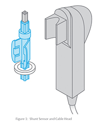
The fluorescent dyes are housed in the shunt sensor, a disposable that is placed directly into the extracorporeal circuit. Each shunt sensor contains four micro sensors — one each for pH, pCO2, pO2 and potassium. The micro sensors are excited by appropriate wavelengths of light, generated by light emitting diodes (LEDs) in the cable head. The cable head couples with the shunt sensor as shown below in Figure 1. The micro sensors in the shunt sensor emit fluorescent light of varying intensities in response to the LED light generated by the cable head, depending upon the concentration of the substance being measured (pH, pCO2, pO2 and potassium).
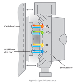
The fluorescent light emitted is measured by photo detectors that also reside in the cable head. These measurements are converted and then displayed on the monitor in the appropriate units of concentration. Figure 2 shows a representation of the LED light, and the fluorescent light emitted.
pH Sensor Design
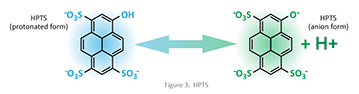
The pH sensor element is a cellulose matrix onto which a fluorescent dye (8-Hydroxypyrene-1,3,6-Trisulfonic Acid (HPTS)) is covalently attached. The fluorescent dye is a weak acid whose anion and protonated forms have different excitation wavelengths. Weak acids do not completely dissociate or fully ionize when dissolved in water, so both the anion and protonated forms of the acid will be present. See Figure 3 for the chemical structure of HPTS.
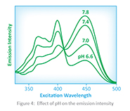
Another important fact is that the degree of dissociation is dependent on the pH of the solution. Therefore, the pH of the solution can be determined by measuring the emission intensity of the different excitation wavelengths produced by the different forms of the acid that is present, when the sensor is excited by the LEDs. The effect of pH on the emission intensity of the CDI pH sensor is shown in figure 4.
pCO2 Sensor Design
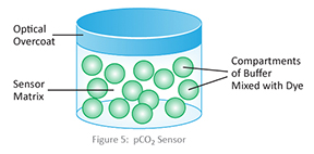
The fluorescent CO2 sensor is essentially a pH sensor that has been enclosed within a hydrophobic membrane that is permeable to CO2 and impermeable to H+. CO2 will equilibrate across the membrane, decreasing the pH in the internal compartment. This combines with water to form carbonic acid and produces a corresponding change in the emission intensity that can be correlated with a pCO2 value. Figure 5 depicts the structure of the pCO2 Sensor.
pO2 Sensor Design
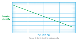
The pO2 sensor consists of an oxygen quenchable dye, which means that the dye will give up some of its absorbed energy to the oxygen molecules in the environment rather than release the energy as fluorescence. Thus, as the concentration of oxygen increases, the fluorescence emission proportionally decreases, and the amount of oxygen can be measured. Figure 6 shows the relationship between pO2 and the emission intensity.
Potassium Sensor Design
The potassium sensor is made of a specific dye which reversibly binds to potassium ions. The binding action changes the structure, which results in an increase in the fluorescence, which can be detected, measured and related to the potassium concentration in the blood.
Interesting facts regarding the potassium sensor:
- The measurement is dependent upon the pH and the sodium concentration in the blood. The pH must be between 6.8 and 9.0, and the sodium must be between 120 and 160 mmol/L. Values outside these ranges can interfere with the measurement of potassium by the CDI Systems.
- The dye used in the sensor is subject to photo degradation, meaning that it loses functionality when exposed to light. Exposure of the sensors to light from the LEDs is a critical process in obtaining the measurement. For this reason, potassium readings are taken every six seconds — rather than every one second as for the pH, pCO2 and pO2 readings — and the photo degradation is accounted for in the calculation.
Conclusion
By understanding the unique technologies offered by Terumo, such as optical fluorescence, perfusionists can make informed choices about the products they use and the patient care they deliver. CDI Systems are the only blood parameter monitors that use optical fluorescence technology to monitor pH, pCO2, pO2, and potassium in extracorporeal blood. Terumo is a leader in innovation and was ranked number 14 out of the top 100 global companies by Forbes magazine on its "World's Most Innovative Companies" list.
Future issues of "Quarterly Updates in Optimizing Cardiac Surgery" will continue to focus on the unique and innovative technologies that are at the heart of Terumo products.
References:
- Hansmann, D, et al. (January, 1988). Practical perspectives on the in vitro and in vivo evaluation of a fiber optic blood gas sensor. Proceedings of SPIE – The International Society for Optical Engineering. 906, 4-10.
- Kees Mahutte, C, et al. (April, 1990). Progress in the Development of a Fluorescent Intravascular Blood Gas System in Man. Journal of Clinical Monitoring. 6(2) 147-157.
- Miller, W, et al. (October, 1988). Continuous In Vivo Monitoring of Blood Gases. Laboratory Medicine. 19(10) 629-635.
- Miller, W, et al. (1987). Performance of an In-Vivo, Continuous Blood-Gas Monitor with Disposable Probe. Clinical Chemistry. 33(9) 1538-1542.
- Tusa, J, et al. (September, 1986). Fiber optic microsensor for continuous in-vivo measurement of blood gases. Proceedings of SPIE – The International Society for Optical Engineering. 713, 137-143.
- Yafuso, M, et al. (1989). Optical pH measurements in blood. Proceedings of SPIE – The International Society for Optical Engineering. 1067, 37-43.